
Banding Instructions
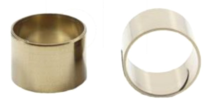
Constant Force Spring Band
Application
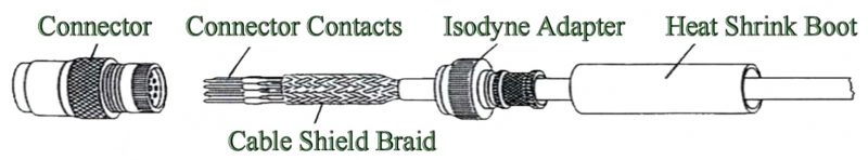
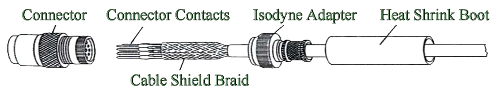
The Isodyne tool-less brain termination system is intended to terminate the cable shield braids and the gross over-braid to military or commercial connectors.
Typical Spring Adapter Cable Termination
Installation Procedures
View more backshell installation videos.
- Assemble the cable making sure a minimum length of 1/2 inch of shield braid is available to go under the constant force spring band.
- Before inserting connector contact, slider the heat-shrink connector boot onto the cable followed bu the Isodyne Adapter.
- Position the heat-shrink boot, Isodyne Adapter and shield braid out of the way and insert the connector contacts. Depending on the shield braid size it can either be folded back onto itself or bunched up accordion style out of the way for easy access to the cable conductors.
- Thread the Isodyne Adaptor onto the connector and tighted to the torque value specified in Table 1. The adapter should be initially hand tightened to ensure proper thread and teeth alignment. the tighten with a strap wrench and torque meter to the specified torque. NOTE: See Table 1 for recommended torque values.
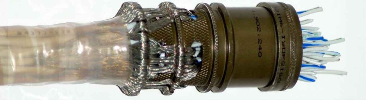
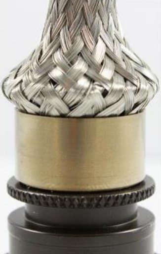
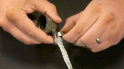
- If inner conductor shields are being terminated, feed them into the adapter and pull them out through the slotted openings. Secure them backwards onto the wire bundle using approved method prior to pulling up the overall shield. Bring the gross cable shield braid up onto the adapter body and form over the read shoulder banding area.
- Open the constant force spring and wrap it around the cable braid that is formed over the band are of the adapter. To open the spring band, hold the coil between the thumb and index finger, locate the end of the band, and slide it backwards with the flat of your other forefinger, until it begins to roll under itself against the rest of the coil, forming a second coil, or loop. Grab both loops from the side using the thumb and forefinger of both hands. Pull open the new smaller loop until you can place this open end onto the adapter, trapping the braid between the spring coil and the end. Secure the adapter and the end and while unrolling the larger coil, until it reached the first end. The spring will now stay in place and can be installed by simply rolling the spring coil arounf the braid covered adapter. See our installation video on our website.
- If utlizing a heat shrink boot (already on the cable), move boot all the way to the front of the banding area/boot groove on the Isodyne Backshell. Shrink so the lip of the boot lands in the groove area, forming a seal with the body of the adapter, and conforming to the banding surface and wire bundle or jacketed cable.

Re-entry Procedure
- Lift up the edge of the constant force spring and push it around the circumference of the assembly to form a coil which then can be rolled around the assembly to remove the spring.
- Carefully lift the cable braid off the adapter and push it back out of the way.
- Remove the adapter and push it back out of the way to facilitate repairs at the connector or exposed conductor area.
- Follow the practices detailed in these banding instructions to reinstall the Isodyne backshell.
Table 1
| Installation Torque Values for Circular Electrical Connector Accessories Accessory Thread Torque ± 5 Inch Pounds |
|||
|---|---|---|---|
| Shell Sizes | Group 1 Light and Medium Duty MIL-C-5015 (MS3100 Series) MIL-C-26482 Series Ⅰ MIL-C-26500 MIL-C-27599 MIL-C-38999 Series I & Ⅱ MIL-C-81511 Series i, Ⅱ, Ⅲ, Ⅳ MIL-C-81703 Series I |
Group 2 Heavy Duty MIL-C-5015 (MS3400 Series) MIL-C-22992 MIL-C-26482 Series Ⅱ MIL-C-28840 MIL-C-38999 Series Ⅲ, Ⅳ MIL-C-81703 Series Ⅲ MIL-C-83723 Series I, Ⅱ, Ⅲ |
Group 2 Values for Hand Held Tool Applications Field Repair Torque |
| 8, 9, A | 35 | 56 | 40-50 |
| 3, 10, 10SL, 11, B | 35 | 76 | 40-50 |
| 7, 12, 12S, 13, C | 40 | 108 | 40-50 |
| 14, 14S, 15, D | 40 | 116 | 50-60 |
| 16, 16S, 17, E | 40 | 116 | 50-60 |
| 18, 19, 27, F | 40 | 116 | 50-60 |
| 20, 21, 37, G | 80 | 136 | 80-90 |
| 22, 23, H | 80 | 136 | 80-90 |
| 24, 25, 61, J | 80 | 136 | 80-90 |
| 28, 29 | 120 | 148 | 120-130 |
| 32, 33 | 120 | 148 | 120-130 |
| 36 | 120 | 148 | 120-130 |
| 40 | 160 | 164 | 150-170 |
| 44 | 160 | 164 | 150-170 |
| 48 | 160 | 164 | 150-170 |
Splice Kit Installation Instructions
This series walkthrough covers the recommended processes for the Isodyne Splice Kit Series. These processes can be used for each configuration and cable diameter size. These processes describe an installation using twister, shielded cabled and a gross over-braid. For installations utilizing different components, please contact Isodyne directly for more information.
Isodyne splice kits can be used for can;e bundle repair, or for managing breakouts in cable assemblies allowing for re-work ad downstream conformance. These processes will apply to both uses. If using the pass through without individual shield management, steps one through seven will not apply.
Step 1
If using the slot for individual ground management, strip the outer jacket from each twisted pair allowing access to the individual shield.
Step 2
Once the individual shield is exposed for each cable, push the shield toward the base of the strip to create a “window” in the braid near where the insulation begins.
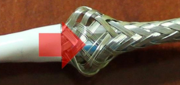
Arrow pointing to “window”
Step 3
Pick the conductors through the “window” and pull the shield to the side to create a shield “pig tail”. Do this for each cable in the bundle.
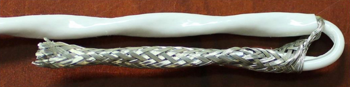
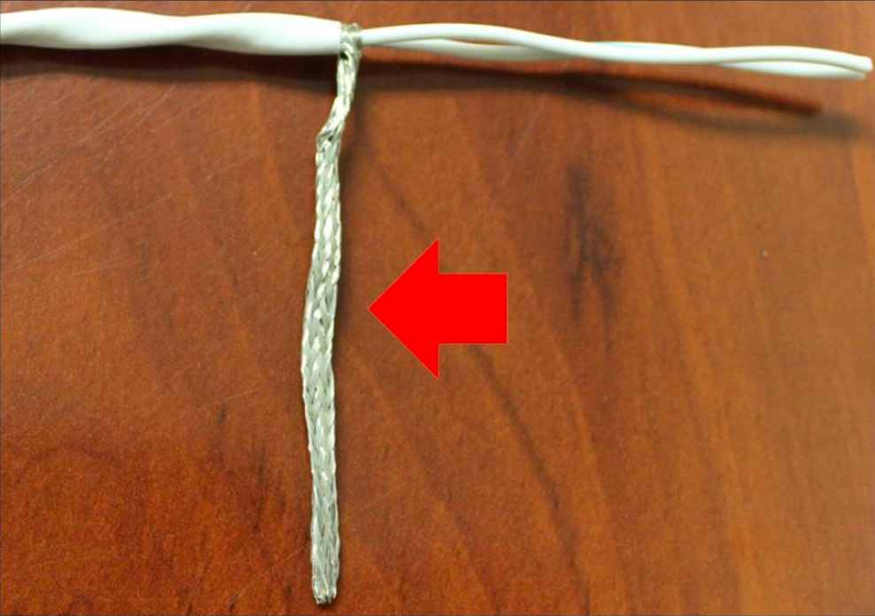
Arrow pointing to “pigtail”
Step 4
With each cable bundle prepared, terminate the conductors with your preferred method.
Step 5
Bundle the terminated conductors together while leaving the individual shields to the side.
Step 6
Take on half of the Isodyne Splice Kit and place it beneath the bundle. The route one half of the shields per end through the slot.
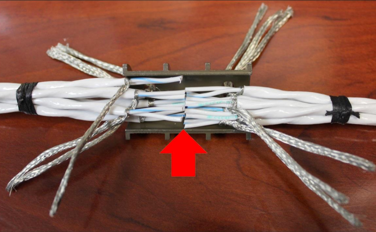
Arrow pointing to site of conductor termination.
Step 7
Take the second half of teh Isodyne Splice Kit and route the remaining shields into the slots as you work the two halves together.
Step 8
Once the two halves are clasped together around the cable bundle and the tongue and grooves are seated properly, fold the protruding individual shields back onto the cable bundle and spot tie. Id using the pass through without individual shield management, there will be no shields to protruding. Clasp the two halves together and proceed to step 9.
Step 9
Now pull the gross over braid towards the splice kit until the leading edge of the braid reaches the innermost shoulder of the first banding surface. Repeat this step for each cable entry.
Step 10
Using the supplied Isodyne Spring Band, open the spring with your fingertips and apply the spring to the first banding surface. Rotate the spring around the banding surface while ensuring the braid is seating neatly beneath the spring. There should be approximately two and one half wraps of the spring. Repeat this step for each cable entry.
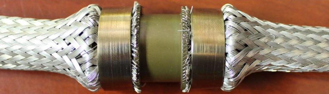
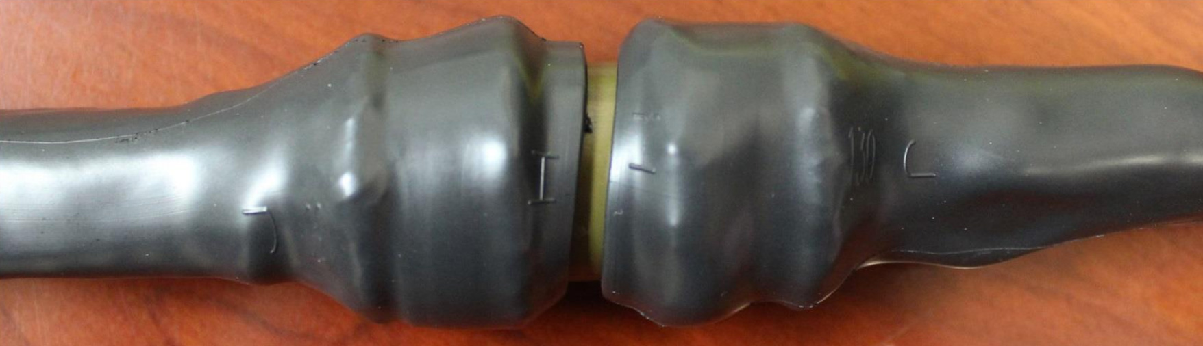
Step 11
This installation is now complete. If using heat shrink molded shapes or sleeving, it can now be applied over the assembled Isodyne Splice Kit.
Download Splice Kit Instructions
Backshell Angle Examples
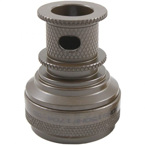
Straight Backshell
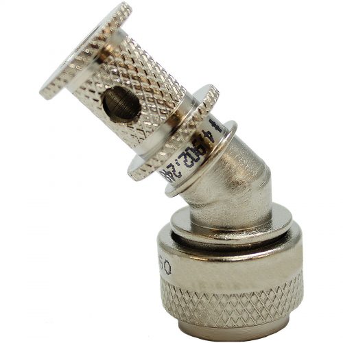
45 ° Backshell
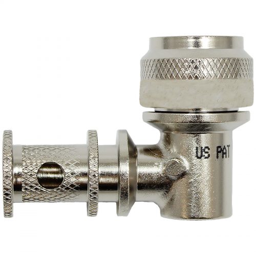
90 ° Backshell